Vintage Mustang Forums banner

Datum line

1 reading
5.3K views 5 replies 3 participants last post by  rusty105  
#1 ·
Hey all

I'm building a 69 Mustang from the floor assembly up.

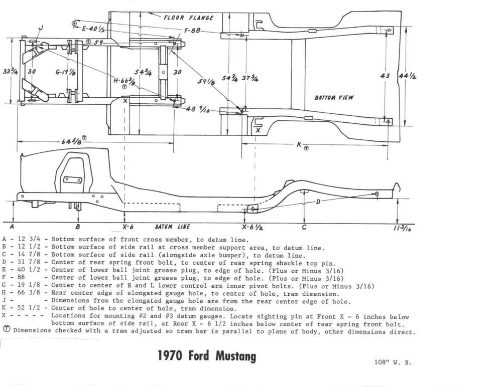
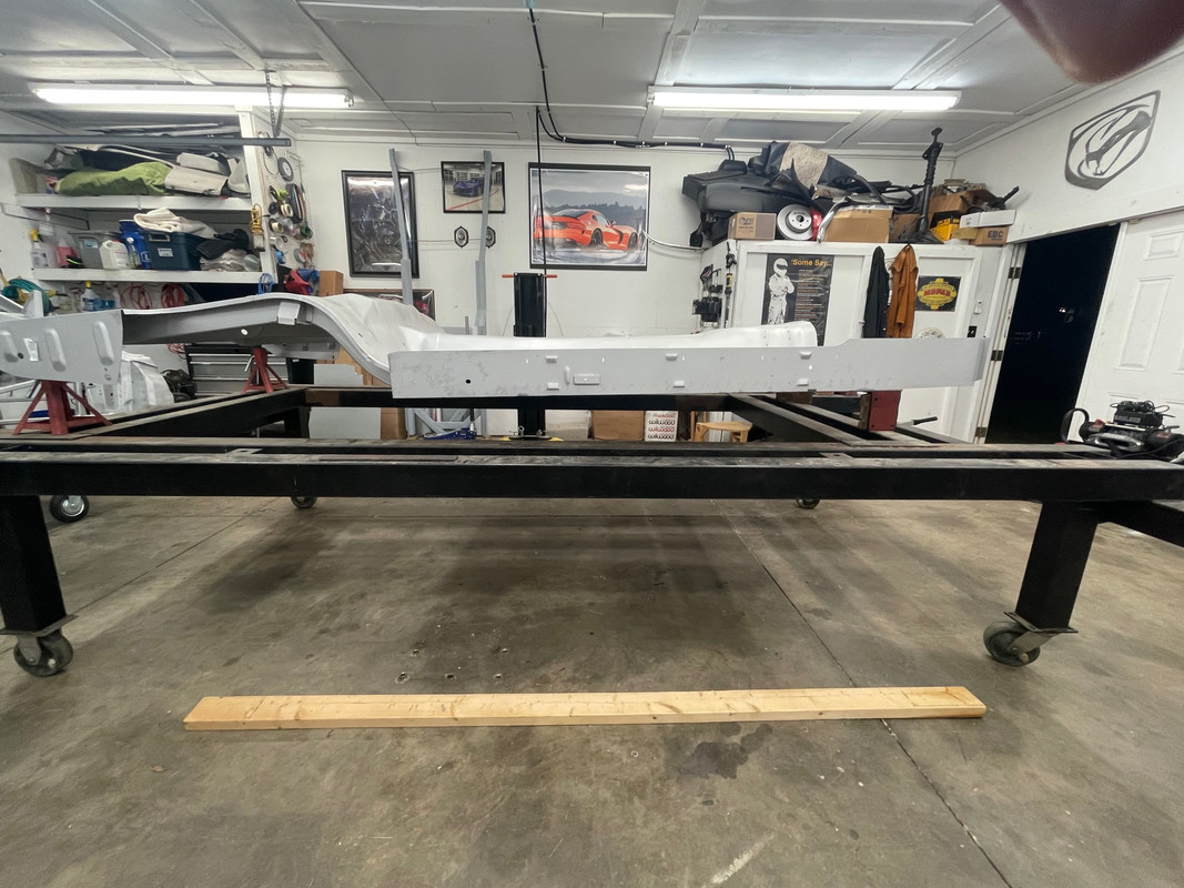
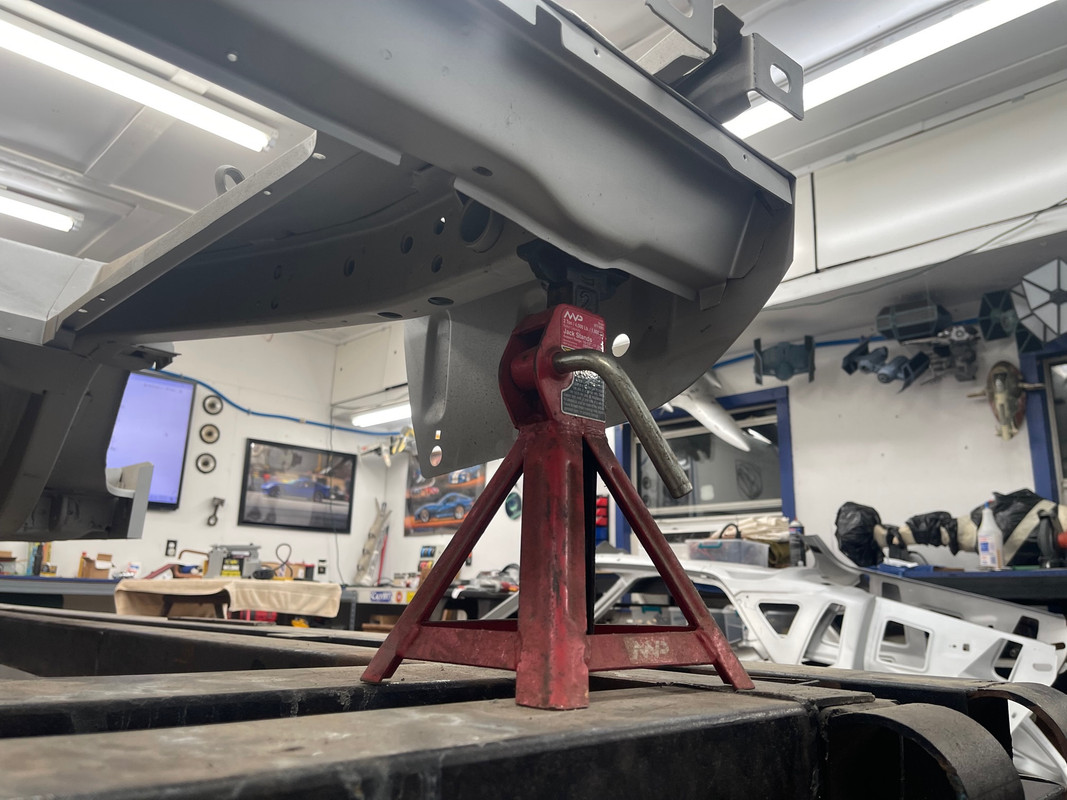
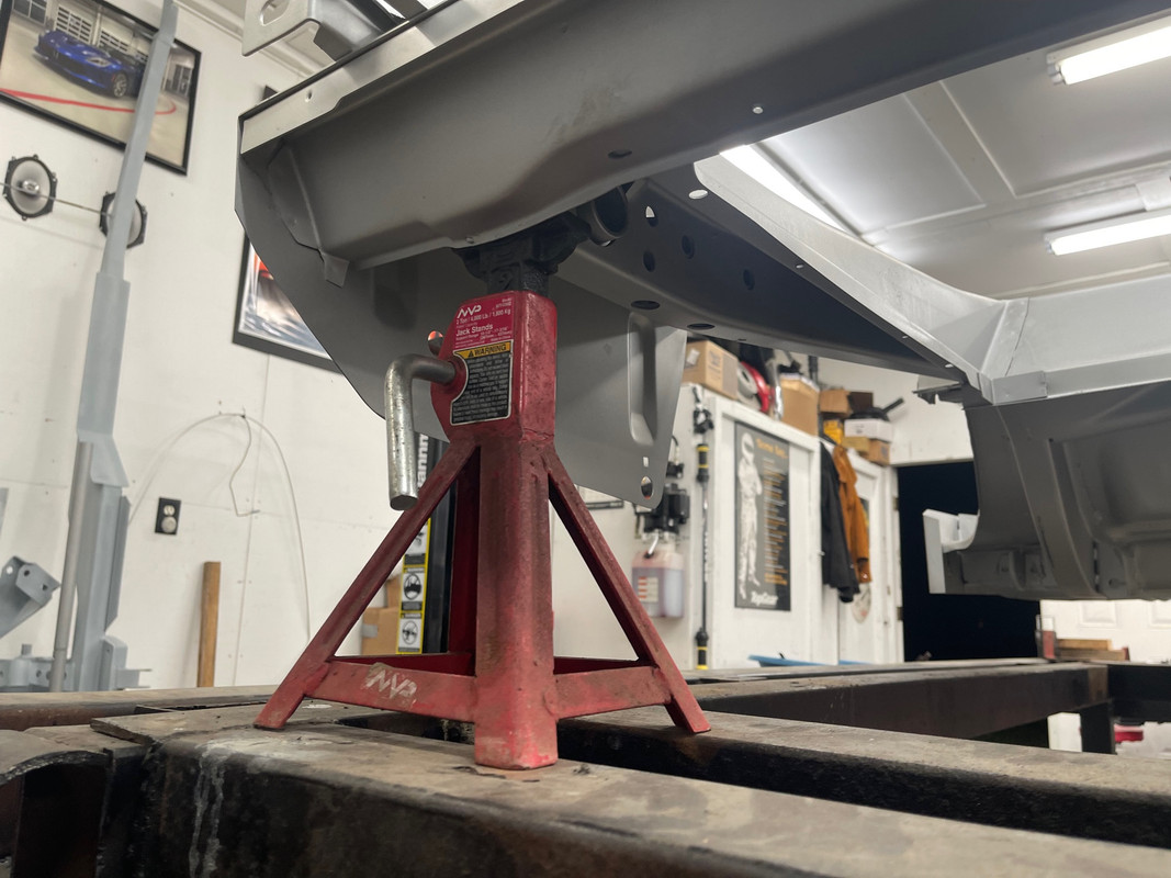
So I'm trying to get this datum line correct based on the diagram.


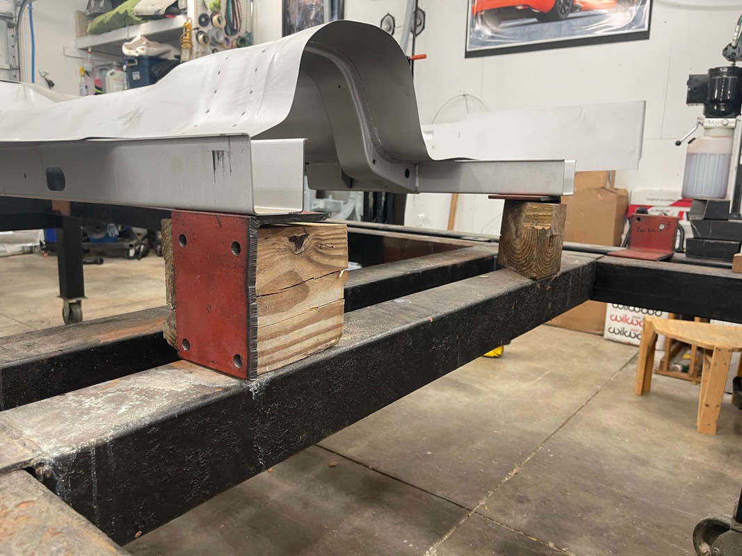
The very end of the rear frame is 11 3/16" high and the very front of the front frame is 6" high. Is it supposed to be at an upward angle like that? The rockers might not necessarily need to be parallel to the datum line and they aren't illustrated on the diagram. Any ideas?


  • Like
Reactions: HoustonGlock
#2 ·
Yes. Also remember these cars were not built extremally precise. The x-6 measurement may change slightly as there is not a an exact location for this measurement. I built a frame to set mine on and started with the front spring mounts, 6.5" up from the datum line & moved everything else around in order to get all measure measurements as close as possible before welding in the front rails. I also added 4" to all of those measurements so I had more room to slide in & weld all of those overheads. The diagram in the 1969 chassis manual has measurements from different points than the 1970. if I recall correctly there are measurements from the steering box holes & the idler arm holes. They use a different datum line location but with a little math they may all be combined to give more points of reference I am stuck in the Denver airport right now or I would post the image of the 1969 diagram. I will try to post that tomorrow sometime.

Another note before you pull your hair out. The chassis diagram indicates the incorrect hole in the front frame rail supports for one of the cross measurements between the rear frame rales & the front frame rail supports.
 
#4 ·
Yes. Also remember these cars were not built extremally precise. The x-6 measurement may change slightly as there is not a an exact location for this measurement. I built a frame to set mine on and started with the front spring mounts, 6.5" up from the datum line & moved everything else around in order to get all measure measurements as close as possible before welding in the front rails. I also added 4" to all of those measurements so I had more room to slide in & weld all of those overheads. The diagram in the 1969 chassis manual has measurements from different points than the 1970. if I recall correctly there are measurements from the steering box holes & the idler arm holes. They use a different datum line location but with a little math they may all be combined to give more points of reference I am stuck in the Denver airport right now or I would post the image of the 1969 diagram. I will try to post that tomorrow sometime.

Another note before you pull your hair out. The chassis diagram indicates the incorrect hole in the front frame rail supports for one of the cross measurements between the rear frame rales & the front frame rail supports.
Yeah it looks like I got it pretty much spot on right now. Thanks for your help.
 
#3 ·
We are both lucky. You get the diagram quickly & I will not forget to go look for it. :) Good old VMF:

 
#6 ·
Good timing on this, I am doing the same with my '65 Coupe Some Body Jig Questions...... Pictures inside

So here is what I have found. The "2X" position measurement of 6" and the "3X" measurement of 6.5" will result in the front being higher than the rear. If you want the rockers to be pretty close to parallel with the Datum line, or Jig frame, use the Ford Factory Manual and its measurements. Those are measured at the leaf spring front bolt (same as the Liskey "3X"), and the steering gearbox / idler arm lower bolt. When I did this I went from higher in the front to darn near parallel. I have been told, by a few people now, to take the Liskey drawings with a grain of salt...

.
Image


Image


Rusty